In the previous LED blinking project we discussed about basic LED blinking concept. Now we take this project one step further. Suppose we want to do this project with 2 LEDs. We want the first LED to light up for 1 second and the second to go out, then the second LED to turn on and the first to go out. We connected the positive end of the first LED to pin 9 of the Arduino and the positive end of the second LED to pin 10, connecting them to the negative end like a circuit with a ground connection.

Now this code is given
|
int led1 = 9; int led2 = 10; void setup () { pinMode (led1, OUTPUT); pinMode (led2, OUTPUT); } void loop () { digitalWrite (led1, HIGH); digitalWrite (led2, LOW); delay (1000); digitalWrite (led1, LOW); digitalWrite (led2, HIGH); delay (1000); } |
You must have understood this program. In the same way we can create LED blinking projects in different sequences using more LEDs.
Arduino input and output
Now we will use any one of the Arduino pin as input and take the output based on it with digital data input. And digital input means that the PIN that we will use as the input pin is either HIGH or LOW.
We are using Arduino Pin 13 as the output pin and Pin 2 as the input pin. Now let’s connect like a circuit.
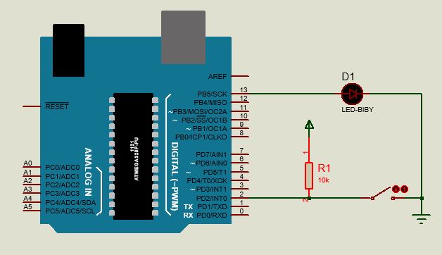
Notice that if the circuit switch is on, there will be a ground connection on pin 2 of the Arduino. As a result, it will remain in the LOW state. Again, if the switch is off, the power will enter pin 2 of the Arduino through the 5V resistor. That means this pin will be in HIGH state. Again,
If the switch is on, Arduino’s PIN number 2 will be LOW.
If switched off, Arduino’s pin number 2 will be HIGH.
Here the resistor is mainly used to resist high current.
Now we want the output to be LOW when the input pin is LOW or the switch is on or the LED is off. Again when the input pin is HIGH or the switch is off then the output is HIGH or the LED is on. For that we uploaded the following program to Arduino.
|
int led = 13; int input = 2; int state; void setup () { pinMode (led, OUTPUT); pinMode (input, INPUT); } void loop() { state = digitalRead(input); digitalWrite (led, state); } |
Here we have declared a total of three variables, including a new state variable. We have used pin 13 as the led variable as the output pin and pin 2 as the input variable as the input pin.
Now a new variable is state. Which is new to you. We are going directly to the void loop () function. Here we have used a new function in the state variable. That is, digitalRead ().
The function of this function is to read the status of any Pin B variable (whether it is HIGH or LOW). For example, digitalRead (input) will read the function here, input or pin number 2 has HIGH or LOW. If there is HIGH, then the value of state variable will be HIGH. And if there is LOW, then the value of state variable will be LOW. Then we have digitalWrite (led, state); Used. That is, whatever the value of the state variable will be, it will be the value of the 13 numbered pin or led variable. E.g.
If the circuit is switched off, the value of input is HIGH. Then state = HIGH. So digitalWrite (led, HIGH); Or led pin will HIGH. That means the LED will light up. Similarly, if the switch is on, the LED will be switch off.
Written
Jeion Ahmed
Electrical and Electronic Engineering (EEE)
Chittagong University of Engineering and Technology (CUET)