
Using Arduino’s above input output project we can make a person’s presence detector or a thief-catching machine. For which we need all the components-
- PIR sensor.
- Arduino board.
- Jumper connection.
- Bread board.
- Buzzer.
Sensor Connection
The PIR sensor does not give any output when everything is stationary in front of it. But if an object with movement is present, it will give 5V output which we can also call digital HIGH. And if such an object is not present or everything in front of it is stationary, it will be in LOW state or will not give any voltage output.

Figure: PIR Sensor
Notice that the sensor has 3 pins. Of these, we will supply 5-12V with positive edge in VCC and negative edge in GND. If there is nothing in front of the sensor, its OUT pin will not give any output or will remain in LOW state. And if something moves in front of the sensor or it sees any movement, the OUT pin will be in HIGH position or it will give 3.3V output. With this voltage we will play a Buzzer. Only then will our desired project be created.
Notice, the PIR sensor has two potentiometers. Whose name-
- Delay Time Adjust.
- Distance Adjust.
3. Delay Time Adjust: After receiving the presence of the object in front of the sensor, the length of the OUT pin will be HIGH or the Buzzer will play, the potentiometer is turned to fix it. This can be done from 1 second to 5 minutes.
4. Distance Adjust: The limit of how far the sensor will be kept under observation is adjusted by turning it.
5. Now we want the Buzzer to play when the OUT pin of the sensor is in HIGH state, and when it is in LOW state, the market will stop. For the project we connect like before circuit.
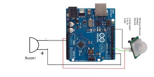
Arduino uses any two GND pins, one with the negative edge of the BUZZER, the other with the GND pin of the sensor. This pin is then connected to the Arduino’s 5V Power pin to power the VCC pin of the PIR sensor from the Arduino board. Now the main thing is that we have connected the OUT pin of the PIR sensor to the 5th pin of Arduino, and the positive end of the BUZZER to the 2nd pin of Arduino.
So our job will be, when the OUT pin of the Buzzer or the 5th pin of Arduino will be in HIGH state, then the positive edge of the Buzzer or the 2nd pin of Arduino will be in HIGH state. Again when the OUT pin of the Buzzer or the 5th pin of Arduino will be in LOW state, the positive edge of the Buzzer or the 2nd pin of Arduino will be in LOW state. And if the Buzzer has a positive pin HIGH, the Buzzer will ring. Then we upload the following code to Arduino.
|
int buzzer = 2; int pir = 5; int state; void setup () { pinMode (buzzer, OUTPUT); pinMode (pir, INPUT); } void loop() { state = digitalRead(pir); digitalWrite (buzzer, state); } |
According to the previous project, the code must be understood, whenever the PIR sensor will output or HIGH, the Buzzer will be HIGH. That means the Buzzer will ring. You can also use LED instead of buzzer if you want.
Written
Jeion Ahmed
Electrical and Electronic Engineering (EEE)
Chittagong University of Engineering and Technology (CUET)